|
||||||||||||||||||
|
There are plenty of places on the web that give lots of in-depth information on how valves work so the following is put in simple, quick terms so as not to bog you down with too much detail. Lack of detail isn't always a good thing and can lead to misunderstanding. Therefore, if you wish to become an expert in the subject, the following should be looked upon as a mere starting block.
Here we will be looking at triode valves, thought to be the best operating mode for audio use.
What does a valve do?
You may be able to guess from its name, a valve allows current to flow through it that can be varied by applying variable voltage across its grid - it acts like an electrical valve. It can therefore be referred to as a voltage controlled current amplifier.
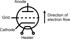
Let's look at a general diagram:

Basically, the cathode emits electrons and the anode receives those electrons. The purpose of the grid is to control the current flow from cathode to anode.
The heater helps the cathode to emit electrons. The exact chemistry is beyond the scope of this article. So, the cathode cannot emit electrons until the heater has warmed and is the reason why valves need a warm-up period to get started, and can be heard for a short period after being switched off. The cathode can also share one of the heater's contacts; when this is the case the heater is then usually referred to as a 'filament' instead.
Some valves deviate from the above diagram. For example:
- Some have multiple grids.
- Some have only 4 pins - the cathode sharing one if the heater contacts.
- Some combine a number of valves within a single enclosure.
- Some have extremely complex internal architectures.
The voltages required can exceed several hundred volts so safety must be adhered to when assembling or servicing valve equipment.
All this happens within a vacuum and couldn't really be simpler.
Simplicity
Simplicity is an all-important feature of valve amplification. Some valves are extremely linear over the audio bandwidth (and beyond). Because of their 'natural' linearity, few complementary components are required. In fact, one of the arts employed by many of the best sounding valve amplifier designs is to use as few a number of components as possible (which also allows you to spend more on the quality of those components).
The minimisation of components is very much required in Hi-Fi amplification design because every component that interacts with the signal path can only degrade that signal - having its own 'sonic signature' that is imparted to the signal. Because the original signal is what we are using as a reference for the source of the amplification, we want to leave it as much intact as possible. Even a single resistor can affect a signal's sonic signature so selection of components and their quality is of great importance and should be selected based mainly on their sonic neutrality (cost is however greatly variable here).
Distortion
Valve amplifiers distort in a different way from most transistors. Valves tend to produce 2nd harmonic distortions; whereas, transistors tend to produce 3rd harmonic distortion. Obviously, whichever type, we always try to reduce the amount of distortion to a minimum but most amplifiers will under certain circumstances produce a little audible distortion.There is a big difference in a valve's distortion as apposed to a transistor's. The transistor's 3rd harmonic distortion is quite nasty to the ear. A valve's 2nd harmonic distortion, however, can actually be quite pleasant on the ear but still, it must be kept to a minimum.
Both valve and transistors produce other orders of harmonic distortion, of course. As a general rule, however, valves tend to produce distortion closer to the fundamental frequency whereas transistors can distort well away from the fundamental; in the higher orders. Higher order distortion is closer to signal related hiss although the higher the order, the more likely the distortion will lie outside the normally accepted audible range.
Don't get caught up in harmonic distortion figures when choosing an amplifier. These figures are usually totally irrelevant (as are many other technical specification figures) to the perceived quality of the actual output. Some of the best amplifiers in the world don't measure well but sound incredible.
Transfer Characteristics
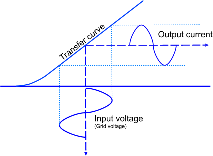
Depending upon certain variables such as the potential difference between the cathode and anode, the load that the valve is to drive, the load's impedance, the valve's inherent linearity etc, we end up with a transfer curve. Somewhere along the transfer curve will be an ideal central position for the input voltage.

Obviously there are many more factors and considerations that go into an actual implementation but I am simply outlining the basics here.
Related Links
The following are external sites where more information about valve theory may be accessed for those who wish to learn more. These links will open in a different window.
| Electrical Fundamentals - Vacuum Triodes |
| The Grounded-Cathode Amplifier |
|
|
