|
||||||||||||||||||

|
The driver board is the most complex board to construct. Perhaps the most important thing to remember is to not solder the heater pads of the valve bases at this stage, as connection to these will be dealt with at a later time. The volume control will also be dealt with later (the upgraded TDK pot requires connections via wires).
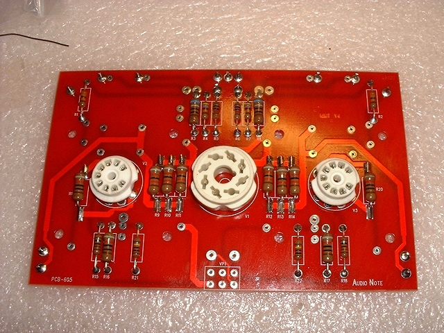
The first thing to be soldered was the valve bases (I fitted the small ones first). It is important to ensure that they are pressed down as far as possible to make good physical contact with the board and are also as level as possible. With the small valve bases especially, the connectors should be pulled through and bent over slightly before soldering so that there is as little play as possible. This is done because as the connector is used (i.e. valves are inserted and pulled out) there will be as little movement as possible - thus making the assembly last through lack of wear etc.
Next the connector pins were fitted anywhere there was to be an interconnect lead, and soldered from the underside.
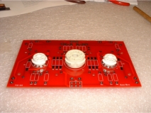 Valve bases have been soldered into position. |
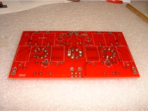 Board from underside - note that any heater pins have been left unsoldered for now. |
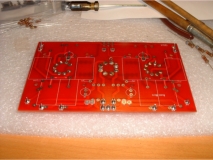 Pins have now been soldered into place. |
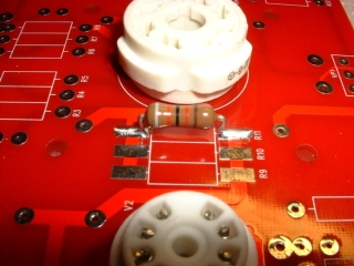
Next up were the resistors. Some of the resistors are surface mounted like the ones in the power supply board.
 Here, I am using some Blu-Tack to hold the resistor in-place while it is soldered. |
 Finished result. |
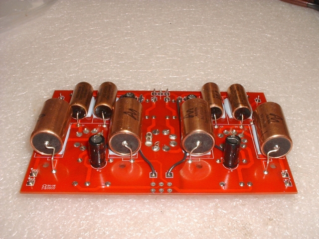
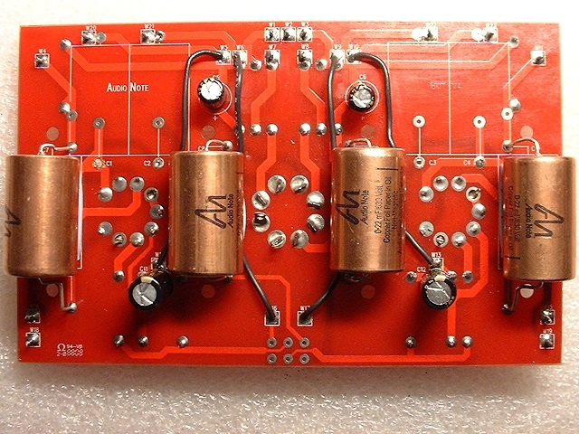
Next, it was time to fit the capacitors on the other side of the board. First there are 4 small electrolytic ones (Black Gates in this case) - these must be orientated correctly. After these, it was time to fit the AN copper foil capacitors.
What surprised me the most about these was their weight. They are quite heavy and have a conductive body. They come with solid silver leads on them too; so the leads are also quite soft. Also, the leads have to be bent into a rather awkward shape; bending to the side to avoid board screws etc.
Putting these facts together, it occurred to me that on their own these capacitors would not be very secure and could possibly move around if not secured further, especially if the unit was ever jolted and with them having conductive bodies, other tracks could be touched. Another danger, because of the conductive bodies, is that of the leads themselves could short on the bodies. I have seen tie-wraps being used in such situations but there are no unused holes on the board and I didn't really want to make any, so my solution was to use a bed of Blu-Tack for the capacitors to sit on. So, after initially bending the leads into shape, the capacitors were pushed firmly into the Blu-Tack and the leads pulled as far as was allowed from under the board. This proved to be highly effective and they are very stable in their positions.
To finish off the board (for the time-being) four links have to be made.
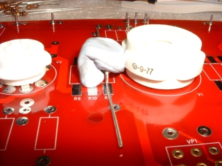
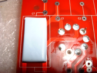 A bed of Blu-Tack ready for the copper foil to be pushed onto. |
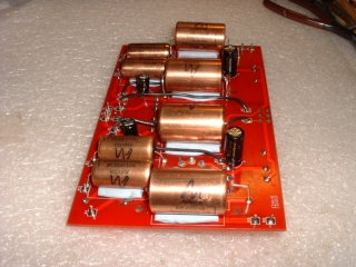 All copper foils inserted. |
NOTE: Before I came to fit the driver board, AudioNote Kits contacted me and informed me that they were having problems with the smaller 0.015uF copper foil capacitors. They had had a number of them, in the same batch, blowing in people's kits about after about 10 hours use. I waited until it was investigated further. The consensus of opinion was to remove those capacitors altogether as they were deemed to be unnecessary (they were there to reduce the possibility of hum in the original design). I therefore set about de-soldering and removing those capacitors from the board.
I have been asked many times where Blu-Tack can be obtained from over the net. I discovered that RS Components sell it (part number 342-4500).
|
|