|
||||||||||||||||||

|
Snubber circuit
The first thing to do is to solder a snubber circuit across the 400-300-0-300-400 wiring. This joins together both of the 400v taps via a capacitor in series with a resistor.Doing this first should make the following wiring easier to achieve.
Planning the wiring
Looming the wires from the secondary required a little planning so I drew a diagram for the purpose - and here it is:
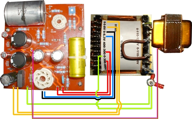
I also included the choke leads and remaining ground leads (i.e. the ones requiring chassis earth).
| Wire(s) | Description |
|
|
There are 2 earth wires: 1. GND on PSU board to Earth Tag. 2. 0v on 400-300-0-300-400 taps to Earth Tag. |
|
|
These two wires go from terminals marked 13v6 on the PSU board to the 8 and 8 taps of the 8-0-8 winding. Note the 0v tap of this winding is not used. |
|
|
These two wires go from the terminals marked 300 and 300 on the PSU board to the 300v taps of the 400-300-0-300-400 winding. |
|
|
These two wires connect the filament wires of the valves. Black connects pin 2 of the 6X5 to 0v of the 0-6.3 winding and Blue connects pin 7 of the 6X5 to 6.3 of the same winding. These will be attached to one of the valve bases on the underside of the board. |
|
|
These two wires are from the choke and connect to the two terminals marked CH on the PSU board. |
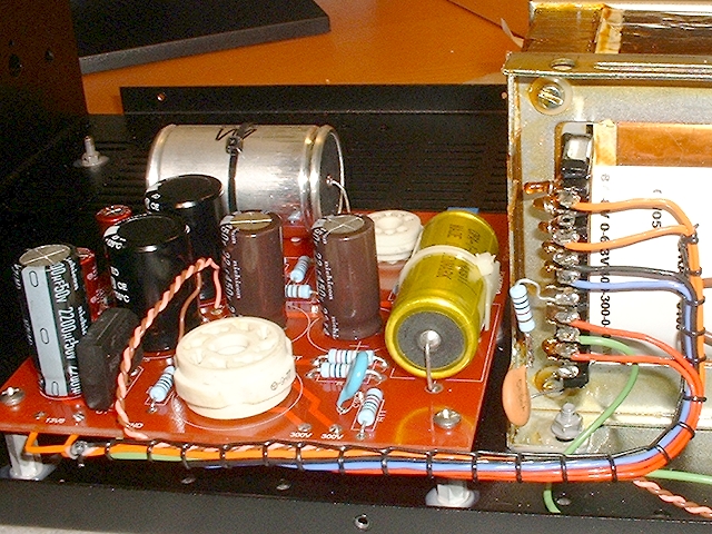
Implementation
I began by soldering the relevant wires to the PSU board. I then laced back toward the transformer; including the necessary wires as I went along.Now, because most of the wires had to 'turn a corner', I continued to lace in a straight line, estimating where each would exit the loom. Fortunately this worked out well. Once the lacing was complete, the wires were bent into place and soldered.
|
|