|
||||||||||||||||||

|
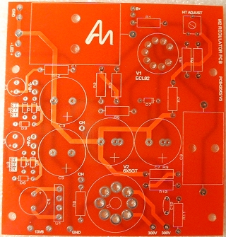
The first thing I decided to do was build the M2 PSU board. This is a standard double-sided printer circuit board.
 |
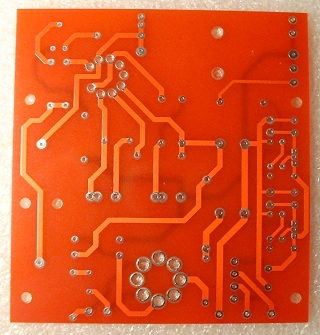 |
| Here is the unpopulated board from both sides. | |
I began with the smallest components (i.e. the ones that stand lowest off the board's surface) ending with the 'highest'.
Notes on the valve bases
When soldering the two valve bases, there are two pins on each that should not be soldered at this time because they will have A.C. leads from the mains transformer soldered to them later. These are the heater pins.Ensure that they are, and remain, perfectly flushed to the PCB surface.
So that it remains solidly in place, it helps to pull the tags through and bend them over slightly before soldering. This ensures that there is not enough room (or play) for the valve bases, or their pins, to move up or down when replacing valves; hopefully increasing the life of the unit through reduced ware and tare.
Below is some video footage showing the process of fitting the valve bases.
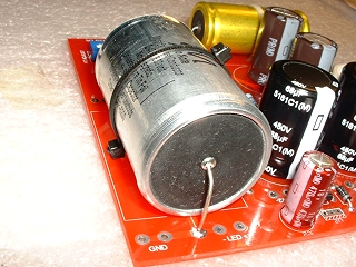
The large capacitors
The Jensen capacitor is slightly too long for its position on the board so its leads must be bent under its body. You should, therefore, secure this capacitor in position. To do this, I rested the body on a thin bed of Blu Tack, which was just thick enough to provide clearance of the leads from the body. Then, I used a tie wrap to secure it. Leads touching the body is not really a problem here because the body is insulated with a covering, but I don't know how much heat will be generated at that position yet - so better to be safe...The Audio Note tin capacitor provided another problem; I didn't have any tie wraps long enough to go around it. I got round this problem by chaining together two tie wraps - I've never thought of that before. This capacitor does have a conductive body so it is essential to secure it well so that there is no danger of the leads touching the body; especially if the unit gets jolted.
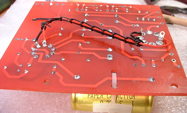
The filament wiring
The filaments of both the valves on this board share the same AC supply. They are, therefore, joined together; ready to accept the wires from the transformer. Lacing the wires meant that the leads could be permanently moved (bent) into a position away from the surface of the board to avoid shorts.
The completed board
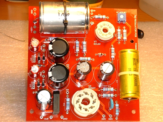
I was hoping to have used PCB pins so that I could solder leads onto them from the upper side of the board. However, unlike the boards from the Kit1, the holes in this board were the wrong size to accept the pins that I have.
So, this board was very straightforward to construct. One thing to note from experience is that when soldering the pot (variable resistor) shown in the top right-hand corner, you should make sure you solder the legs quickly because too much heat can easily damage these delicate devices.
|
|