|
||||||||||||||||||
|
Now that the first part of the testing was complete (i.e. the simple resistance checks on the phono board), the next stage is to wire up the phono board to the power supply and do some voltage checks.
Before that, however, I decided it was time to fit the central screen. This acts as an electro-magnetic shield between the power supply and phono board (and input/output cables).
|
|
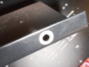
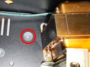
The screen should have a good electrical contact with the earthed chassis. To enable this, one of the fixing holes has had its surrounding paint removed - exposing the bare metal. There is also a corresponding exposed portion of the chassis that is intended to mate with it.
Of course there is the thickness of the paint to consider, so I decided to add a washer between them - fortunately washers of just the right size are provided. This meant adding a washer to each of the three securing holes so that the screen is level. |
Having fitted the screen, it was time to wire the phono board to the power supply.

There are basically four connections here:
Ground connection
I connected this to the leg of one of the resistors.
HT connection
This connects to one of the HT terminals. I relied on the HT track to join the left and right feeds.
Filament supply for input valves
I connected this to the two filament terminals that I made on the top of the board. Again, I relied on the filament tracks to join the supplies between the two valves.
Filament supply for output valves
This is wired to the underside of the board - directly onto the filament terminals on the output valve base's pins.
Once these connections were made, I could switch on and measure some test voltages. The manual (at time of writing) provides 4 test voltages per channel that are measured across various resistors. These measured as follows:
| Left Channel | Expected voltage | Measured voltage |
| R7 | 100v | 117v |
| R15 | 130v | 142v |
| R19 | 1.6v | 1.5v |
| R8 | 1v | 1.0v |
| Right Channel | Expected voltage | Measured voltage |
| R9 | 100v | 114v |
| R16 | 130v | 142v |
| R20 | 1.6v | 1.9v |
| R10 | 1v | 0.8v |
Valve Shields
I was happy to proceed, so I then switched off and fitted the valve shields. These are made from aluminium and have springs inside them. They fit over the valves and fix onto the valve shield bases that I fitted to the valve bases earlier. The idea of the valve shields is to reduce microphonic effects such as audio feedback.
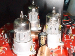 Valves awaiting their shields |
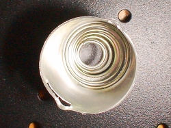 Here you can see the spring inside a valve shield |
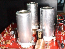 Valve shields have now been fitted |
Faceplate and LED
Now I fitted the faceplate. It is usually a good idea to leave this to near the end of a build because there is much less chance of marking the faceplate this way (something you would have to look at every day and regret). This is held on by 4 black screws. The faceplate itself looks great and is finished in gold lettering. Being extremely reflective, however, makes it really difficult to photograph - making any reflections look like markings!
|
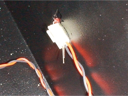
Once the faceplate was fitted, the LED could be secured in place. I used a 2-part epoxy for this - holding the assembly in place with a couple of pieces of insulation tape while it set overnight.
|
Inputs and Outputs
The last thing that needed doing before I could plug the phono stage into my system was to wire up the input and output connections. Before I could do this, the RCA connectors had to be fitted to the back of the chassis.The silver plated phono RCA connectors are easy to fit. The following is an explanation that I have copied from my DAC Kit build...

The washer shown nearest the socket has a lip on it. That washer is fitted onto the RCA socket before it is inserted from the back of the unit. It must be located so that the lip sits inside the back panel hole. This is important because the socket must remain insulated from the chassis. Next the other, non-lipped washer is fitted, followed by the earth tag and finally the nut.
When tightening the nut, you should bear a couple of things in mind. I always orient the sockets so that the 'well' that accepts the hot signal wire is in a position that will accept solder to flow down into it. While you are tightening the nut however, the RCA will want to turn along with the nut so it is advisable to hold the RCA in place with a spanner (or wrench) from the outside of the chassis. The other thing to bear in mind is where you want the final position of the earth tag to be as this too will move around with the nut.
Once the RCA's are fitted, and the earth tags in the correct positions, you will usually want to bend the earth tags outward away from the chassis.
I had opted, as usual, for the AN-V cable for my ins and outs. This is q fairly expensive upgrade but well worth it to me. These silver cables can make a big difference. The cables come pre terminated and cut to the correct lengths.
They are, however, quite delicate and the conductors, once tinned, can easily snap off if bent repeatedly. Therefore, be careful with them. Soldering them to the board terminals can therefore be a little tricky as you really need three hands. To get around this, I used a little trick...
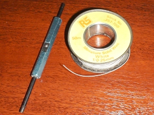 Wire wrapping wire and tool |
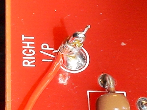 An input wire firmly attached to its terminal using a 'wrap' of wire |
First, I bent the wire to be attached to the board at a 90-degree angle. Next, I took some very thin wire wrapping wire that I had laying around and stripped off lots of insulation. Then I wrapped it around both the input wire and the terminal. This had the effect of putting a lot of pressure on the wire and terminal - achieving a very good mechanical connection without putting any real strain on the wire itself. The last thing to do was to solder them - beats tag soldering!
The other ends are soldered to the RCA sockets.
It is important to note that the ends of the pre prepared cables that use the cable's screen (only one end should be screened), must be soldered at the board end so that the phono stage's ground is used for the shielding.
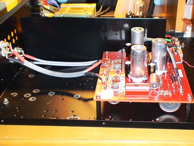
Now fully wired and ready for an in-system test
The only finishing touch to make now was the lid - held on by 10 small screws.
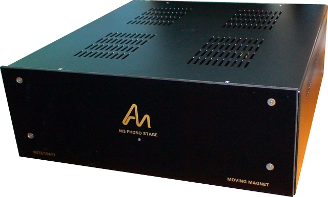
Finished and ready for system testing
System Testing and First Impressions
Always the most nervous part - hooking up to the main system. So the turntable should be connected, its earth wire(s) should be connected to the earth terminal and signal leads connected to the input RCA's. The output should be connected to your amplifier (or pre-amplifier).Always start with the amplifier volume on zero and no signal applied to the phono stage. Then, increase the volume and check for hum. I can safely say that there is none detectable - always a good thing.
Next, put on a record and hope for music. YES, it works! Oh, and how.
The first thing to strike me was that the output is quite high - the phono stage is now on par with the output of my DAC - I like that as it makes comparisons between the two much easier.
After a tentative start, I began to listen seriously to some familiar records and was very pleased with the results. This phono stage is a BIG improvement on its predecessor. It kind of reminds me of the difference between the DAC Kit 1.1 and 2.1 - yes the older one was quite good but the later one is to be taken much more seriously. The sound is much more open and extended, maintaining greater consistency throughout the spectrum than my previous phono stage.
I intend to write a review soon that will go into more depth about the way the phono stage sounds. I am sure that it will go through the usual fluctuations as the components break-in.
|
|
