|
||||||||||||||||||
|
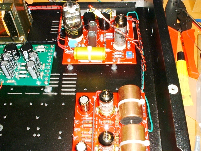
The loom between the M2 power supply board and the analog board couldn't be simpler - so no need to draw any plans for this one.
Included in the loom are:
- One HT lead.
- One earth wire.
- LED leads.
- 2 x filament wire pairs.
The two pairs of filament wires join from the 6v2 pads on the M2 power supply board to pins 4 and 5 on each valve base. Each valve therefore has its own filament supply.
The HT lead joins from the B+ pad on the M2 power supply board to W38 on the analog board. In the previous section I shorted W38 to W39.
The earth wire joins from GND on the M2 power supply board to the central ground bus of the analog board. I could have used W36 but I thought that I would leave that terminal free because it has to accept the signal cable earth, which has quite a hefty earth wire combination.
That leaves the LED wire. I left that floating in mid air because I wanted to leave the fitting of the front face plate to as late a stage as possible to stop it getting marked during the build.

| Time for a Quick Test |
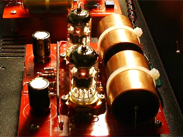
Now that the analog board has been wired to its power supply, we can at least check that the filaments light up as they should when powered on.

Yes, the filaments lit up as expected. Everything looks fine.
I also took the opportunity to adjust the HT voltage now that the HT was in circuit. This is done by turning the small variable resitor on the M2 power supply board. The voltage should be 230v which was easily achieved.
|
|
