|
||||||||||||||||||

|
Now that all the boards are in place and power connected to all of them, all that is left to do is connect up the signal wires and digital board input wires.
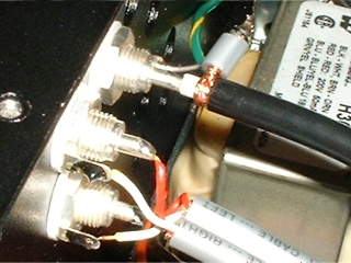
The first job here is to fit the three supplied silver RCA sockets to the back panel.
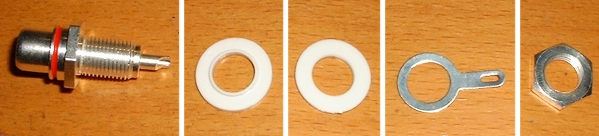
The washer shown nearest the socket has a lip on it. That washer is fitted onto the RCA socket before it is inserted from the back of the unit. It must be located so that the lip sits inside the back panel hole. This is important because the socket must remain insulated from the chassis. Next the other, non-lipped washer is fitted, followed by the earth tag and finally the nut.
When tightening the nut, you should bear a couple of things in mind. I always orient the sockets so that the 'well' that accepts the hot signal wire is in a position that will accept solder to flow down into it. While you are tightening the nut however, the RCA will want to turn along with the nut, so it is adisable to hold the RCA in place with a spanner (or wrench) from the outside of the chassis. The other thing to bear in mind is where you want the final position of the earth tag to be as this too will move around with the nut.
Once the RCA's are fitted, and the earth tags in the correct positions, you will usually want to bend the earth tags outward away from the chassis.
Signal Output Leads
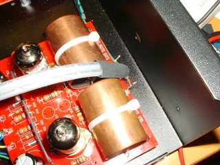
The output signal is carried to the RCA sockets using Audio Note AN-V cable (non signature versions use AN-A unnless AN-V is specified as an upgrade option). I asked for an unterminated piece so that I could terminate it myself (it normally comes already terminated). However, I would only recommend this approach if you have experience with this cable as it can be difficult to terminate.The end that connects to the analog board produces three leads. The central one is made up of the braiding from both wires plus the white groung wires from both channels. Twisted together, these make quite a solid chunky wire. This chunky wire connects to the central earth bus terminal (W36). I tackled this by using a length of very thin wire wrapping wire (uninsulated) to bind the terminal wire to the solid combination wire. I probably used about 10 turns. This created a very solid mechanical connection with very good contact area - this was then soldered.
The remaining two red signal wires were then simply wound around the signal terminals (W35 and W37). This was now easy to achieve because of the solidity of the central connection.
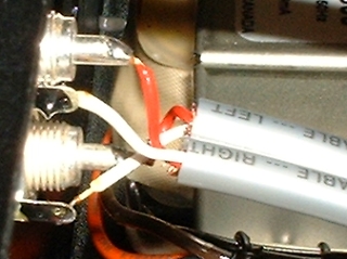
The other end of the AN-V cable connects to the two output RCA sockets. At this end, the braiding is not used and should not connect to anything. It has done its job by being connected at the analog board end by providing an earth shield. Now it should be a simple job of soldering to the output RCA's (red wire live, white wire ground).
|
|
Digital Input Signal Wiring
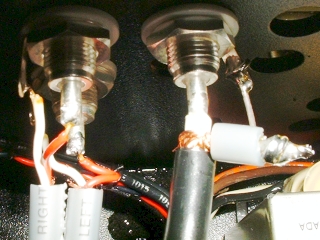
The third RCA socket connects to the digital board's input. The signature board was supplied with a piece of co-ax ready-fitted. All that was necessary was to terminate the other end and connect it to the RCA socket. Because the co-ax was very stiff, it made it a little difficult to orient the wire exactly where I wanted it to go. So, I ended up using a small piece of silver wire that was left over from the analog board build to solder to the RCA earth tag and then twist around the co-ax's braiding.
|
|
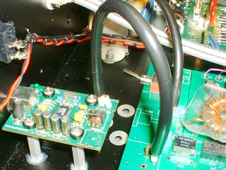
This just left the digital signal link to the USB board. Again, I used a piece of coax to connect it to the digital board.
|
|